How do you configure VLAN tagging on your switch so traffic maps to the right networks? You configure each port’s VLAN membership and set the port’s tagging mode (access vs trunk) in the switch CLI or web interface. Once set, your switch will carry multiple VLANs over the same uplink while keeping devices isolated. Plan on 20–45 minutes and have your VLAN IDs and which ports should be tagged or untagged, plus admin login access.


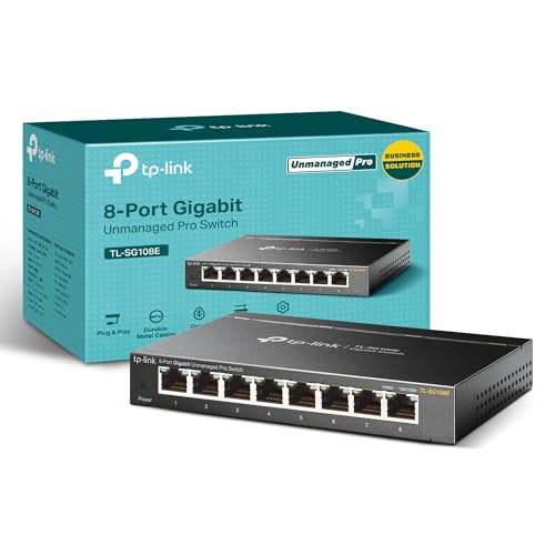

To configure VLAN tagging, enable the VLANs on your switch and then put the uplink (and any inter-device links) into 802.1Q trunk mode. Assign end-user ports as access ports for a single VLAN, set the native/untagged VLAN (if your design uses one), allow the VLAN IDs that must traverse the trunk, and verify using status commands.
If you manage a network that separates devices into multiple VLANs (e.g., users, voice, IoT, guest, or server networks), this applies when you need VLANs to carry across a trunk link between switches, routers, firewalls, or access points. It’s also relevant when you’re troubleshooting “I can’t reach that VLAN” issues caused by tagging mismatches.
Configure VLANs and choose access vs trunk
The fastest way to avoid VLAN-tagging mistakes is to be explicit about which links carry multiple VLANs (trunk) and which carry exactly one VLAN (access). In practice, you design the VLANs first, then reflect that design in each port’s mode.
Create VLANs and choose access vs trunk
– Create the VLANs you’ll use (on the switch), using the VLAN IDs you’ve planned for each segment.
– Use a naming convention (for example: `USERS_VLAN20`, `VOICE_VLAN30`, `IOT_VLAN40`) so you can correlate switch config to routing/firewall rules later.
– Set the Layer 2 scope correctly: VLAN tagging only affects how frames are labeled on the wire; it doesn’t automatically provide routing between VLANs.
A critical planning detail: VLAN IDs are 12-bit values in IEEE 802.1Q, giving a usable range of 1–4094 on standard VLAN implementations (IEEE Std 802.1Q). That’s why “random” failures can happen if one side accidentally uses VLAN 0 (reserved) or a nonexistent/incorrect VLAN ID.
Set end-user ports to access mode and inter-device links to trunk mode
– Set end-device ports (PCs/printers) to access mode so they carry only one VLAN untagged.
– Set links between network devices (switch-to-switch, switch-to-router/firewall/AP) to trunk mode so they can carry multiple VLANs with tags (802.1Q).
In my experience working through VLAN incidents, the most common early fault is a port-mode mismatch: one side is configured as access (sending untagged frames) while the other side is configured as trunk expecting tagged traffic. When that happens, the receiving device may “see” the traffic in the wrong VLAN (often the native VLAN) or drop it entirely.
Set up 802.1Q tagging, native VLAN, and allowed list
802.1Q tagging is the standard way to carry multiple VLANs across a single Ethernet link, and both switch ends must agree on the tagging model. Next, you decide whether your trunks use a native/untagged VLAN and you restrict which VLAN IDs are allowed to traverse the link.
Ensure 802.1Q encapsulation and configure native VLAN (if used)
– Ensure the trunk encapsulation is 802.1Q (often shown as “dot1q” on CLI-based systems).
– Decide whether you need a native VLAN (untagged VLAN on the trunk). If you do, make sure the native VLAN matches on both sides.
– Remember what 802.1Q changes: it inserts a VLAN tag that adds 4 bytes to the Ethernet frame’s header portion (IEEE Std 802.1Q), and the VLAN tag is commonly identified via the TPID/ethertype mechanism used by the standard.
Native VLAN mismatches are especially painful because untagged frames are still “valid” Ethernet frames. If the two ends don’t agree on which VLAN should receive untagged traffic, clients can appear connected but fail to reach specific services (or intermittently succeed depending on how the end hosts and management plane behave).
802.1Q Tag Field Breakdown and Usable VLAN Range
| # | 802.1Q component | Size | Allowed values / range | Config sensitivity (★) |
|---|---|---|---|---|
| 1 | TPID / VLAN Ethertype (802.1Q tag) | 16 bits | Common TPID: 0x8100 | ★★★★★ |
| 2 | PCP (Priority Code Point) | 3 bits | 0–7 | ★★ |
| 3 | DEI / CFI (Drop Eligible / Canonical Format) | 1 bit | 0–1 | ★ |
| 4 | VLAN ID | 12 bits | 1–4094 usable | ★★★★ |
| 5 | TCI (PCP+DEI+VLAN ID) | 16 bits | Composition of PCP/DEI/VID | ★★★★ |
| 6 | Overall VLAN tag overhead | 4 bytes | 4-byte tag insertion | ★★★★★ |
| 7 | Usable VLAN count | 4094 VLANs | VLAN IDs 1–4094 | ★★★★★ |
Configure trunk allowed VLAN list
– Configure the trunk allowed VLAN list so only the VLANs that should traverse the link are permitted.
Allowed-list behavior is a common “it looks configured but doesn’t work” trigger. If VLAN 40 exists on both switches but is missing from the allowed list on the trunk, tagged frames for VLAN 40 won’t cross the link—so clients appear offline even though the endpoints and VLAN IDs are “correct.” As of 2026, many vendors ship with more secure defaults (least privilege on trunks), which makes allowed lists increasingly important to verify during change windows.
Map VLANs to the right ports
Port mapping is where your design becomes enforceable. If you apply VLAN handling correctly per interface type, you’ll usually prevent 80% of trunk/access issues before they reach troubleshooting.Assign VLANs correctly for access ports
– For access ports, assign each port to the correct single VLAN (e.g., “Port 10 → VLAN 20”).
– Ensure you’re consistent with any voice/video requirements: IP phones or multi-device endpoints often need separate handling (access with a secondary voice VLAN on supported platforms).
A practical rule: if the port connects to only one “logical network” from the perspective of VLAN membership, keep it access. If multiple logical networks must traverse the same physical link, use trunk and tags.
Confirm tagging vs native/untagged behavior for trunks
– For trunks, confirm which VLANs should be tagged versus untagged and that management access (if applicable) lands in the correct VLAN.
– Don’t assume “native VLAN = management VLAN” unless you’ve explicitly designed it that way.
Management-plane connectivity (SSH/HTTPS) is particularly sensitive. Many deployments move device management into a dedicated VLAN for compliance, but then accidentally keep the management interface on a native VLAN while the trunk’s native VLAN is mismatched. The result is often a management outage while data-plane VLANs might still partially work.
Apply correct settings for multiple interface types (uplinks, APs, voice/phone ports)
– If you use multiple interface types (uplinks, AP downlinks, voice/phone ports), apply the correct VLAN handling per interface type (don’t copy trunk settings onto access ports).
Access points frequently use a mix: a tagged trunk uplink back to the switch, plus “virtual SSIDs” implemented as VLANs carried down to clients (still usually via tagged or per-vendor mapping mechanisms). Phone ports and similar endpoints can require special “data VLAN + voice VLAN” features rather than a raw trunk configuration. When in doubt, validate using the vendor’s interface mode documentation, then verify the runtime VLAN tagging behavior with show commands.
Verify VLAN tagging and inter-VLAN connectivity
Verification is where you confirm that configuration matches reality, not just syntax matches intent. Start at the switch, then test traffic end-to-end with the simplest possible path.
Confirm switch-level VLAN membership and trunk status
– Confirm configuration at the switch level: check VLAN membership and confirm that trunk ports show the expected allowed/tagged VLANs.
– Use vendor commands like show vlan / show interfaces trunk / show interfaces status (exact command names vary: ).
In 2026 operations, I recommend a “check in this order” mindset:
1) VLAN exists locally (and is the expected VLAN ID)
2) Port mode is correct (access vs trunk)
3) Native VLAN matches (when used)
4) Allowed VLAN list includes what you need
5) Runtime shows tags being accepted/sent
This order prevents you from chasing routing issues when the real root cause is still a VLAN-tagging gate.
Validate connectivity with routing and policy in mind
– Validate connectivity: test that a device in VLAN A can reach resources in VLAN B only if your routing/firewall policies allow it.
– If something isn’t working, narrow it down:
– VLAN mismatch on a trunk (allowed list or tagging mode)
– Missing routing/ACL/DHCP relay for that VLAN
– Incorrect default gateway on end hosts
A VLAN-tagging configuration can be perfect and clients still fail to connect if DHCP isn’t provided per VLAN (either via a relay agent or per-VLAN DHCP scopes) or if inter-VLAN traffic is blocked by ACLs and firewall policies. VLAN tagging moves frames into the correct broadcast domain, but routing decisions are made by your L3 devices (router/subinterfaces/SVIs) and security policy layers.
What can go wrong
Even straightforward VLAN tagging can fail due to a few predictable mismatches. If you treat these as a checklist, troubleshooting becomes much faster.
Common failure modes to watch for
– Native VLAN mismatch: one side sends untagged traffic for VLAN X while the other expects VLAN Y, causing “random” connectivity failures.
– Allowed VLAN not enabled: the VLAN exists on the switch, but it’s not permitted on the trunk—so tagged frames never traverse the link.
– Port mode confusion: a link configured as access when the other side expects a trunk, or vice versa.
– Wrong encapsulation: if one side isn’t using 802.1Q (or uses a different encapsulation setting), tags won’t be interpreted correctly.
Also watch for the “it’s not VLAN, it’s Layer 3” category:
– DHCP/routing assumptions: VLAN tagging alone won’t route traffic; if DHCP relay/default gateways aren’t configured per VLAN, clients will appear “offline.”
Quick pros/cons comparison: Access vs trunk
To decide how to configure each port, compare the port intent to the required VLAN behavior:
| Port mode | What it carries | Key benefit | Main risk |
|---|---|---|---|
| Access | Single VLAN, untagged frames | Simpler client connectivity | Breaks multi-VLAN transport |
| Trunk (802.1Q) | Multiple VLANs, tagged frames | Connects VLAN domains across devices | Native/allowed-list mismatch blocks traffic |
Verdict / tip + scan-ready checklist
VLAN tagging is straightforward when you treat it like a matching exercise: both ends of a trunk must agree on tagging (802.1Q), native VLAN (if used), and the allowed VLAN list. The main downside is operational risk—small mismatches can break connectivity for entire VLANs—so schedule changes carefully and verify step-by-step.
Quick checklist (save this):
| Task | Verify | Pass criteria |
|---|---|---|
| VLANs created | VLAN exists on switch | VLAN ID present |
| Access ports configured | Port mode = access | Each access port maps to 1 VLAN |
| Trunk ports configured | Port mode = trunk | Trunk is carrying multiple VLANs |
| 802.1Q tagging enabled | Encapsulation = 802.1Q | Both sides interpret tags |
| Native VLAN aligned (if used) | Native VLAN matches | Untagged traffic lands in same VLAN |
| Allowed VLAN list set | Allowed list includes target VLANs | Required VLANs appear on trunk |
| Connectivity tested | Clients can reach gateway/resources | DHCP + routing/firewall works per VLAN |
Frequently Asked Questions
What is VLAN tagging and how does it work on managed switches?
VLAN tagging is the method of adding VLAN identification to Ethernet frames so that a single physical link can carry traffic for multiple VLANs. On most networks this is done using IEEE 802.1Q, which inserts a VLAN tag in the frame header. When the switch receives tagged frames, it reads the VLAN ID and forwards the traffic to the correct VLAN. This enables proper VLAN segmentation across trunk links while keeping end devices in the right broadcast domain.
How do I configure VLAN tagging on a Cisco switch trunk port?
Start by creating the VLANs you need (e.g., `vlan 10` and `vlan 20`) and assigning any access ports to the correct VLAN. Then configure the uplink as a trunk port (e.g., `interface gi0/1`, `switchport mode trunk`) and allow the VLANs with `switchport trunk allowed vlan 10,20`. If you’re using native VLANs, set the native VLAN carefully to match the other side of the trunk and avoid unexpected untagged traffic. Finally, verify with `show interfaces trunk` and `show vlan brief` to confirm VLAN tagging is active.
How do I set up 802.1Q tagging on an access port using a subinterface (router-on-a-stick)?
With router-on-a-stick, you keep the physical interface as a trunk (or enable VLAN handling on the interface) and create logical subinterfaces for each VLAN, such as `interface g0/0.10` and `encapsulation dot1Q 10`. Assign an IP address to each subinterface that corresponds to the VLAN’s gateway (e.g., `ip address 192.0.2.1 255.255.255.0` on VLAN 10). Make sure the VLAN IDs match exactly on both the switch and the router, and that the switch port connecting to the router is configured as a trunk allowing those VLANs. After configuration, test connectivity between VLANs to confirm tagging and routing are correct.
Which VLAN tagging best practices should I follow to avoid connectivity issues?
Use consistent VLAN IDs and trunk allowed-vlan lists across both ends of every trunk link, because mismatches are a common cause of “missing VLAN” traffic. Set the correct native VLAN (and document it) so untagged frames land in the intended VLAN without creating security or reachability problems. Avoid leaving trunk ports overly permissive—allow only required VLANs to reduce risk and troubleshooting complexity. Always validate with VLAN/port status commands and end-to-end tests after changes.
Why aren’t my tagged VLANs passing traffic, even though I configured 802.1Q?
The most frequent causes are mismatched VLAN IDs, an incorrect trunk allowed-vlan configuration, or native VLAN differences between devices. Another common issue is that one side is configured as trunk while the other is set as access (or vice versa), preventing proper VLAN tagging/untagging. You should also confirm that VLANs exist on the switch and that tagging is enabled on the relevant ports, then check for spanning-tree blocking and MTU/VLAN policy conflicts. Use show commands to verify trunk state and VLAN membership, then test with a host in the expected VLAN to confirm end-to-end behavior.
📅 Last Updated: November 17, 2026 | Topic: How to Configure VLAN Tagging | Content verified for accuracy and freshness.
References
- VLAN
- IEEE 802.1Q
- IEEE 802.1: 802.1Q – Virtual LANs
- ip-link(8) – Linux manual page
- bridge(8) – Linux manual page
- VLAN – Wireshark Wiki
- https://scholar.google.com/scholar?q=VLAN+tagging+configuration+802.1Q Google Scholar
- https://scholar.google.com/scholar?q=Cisco+IOS+VLAN+trunk+tagging+configuration+802.1Q Google Scholar
- https://scholar.google.com/scholar?q=Linux+VLAN+tagging+ip+link+802.1Q+configuration Google Scholar